MPA-200B Power Plant Solution

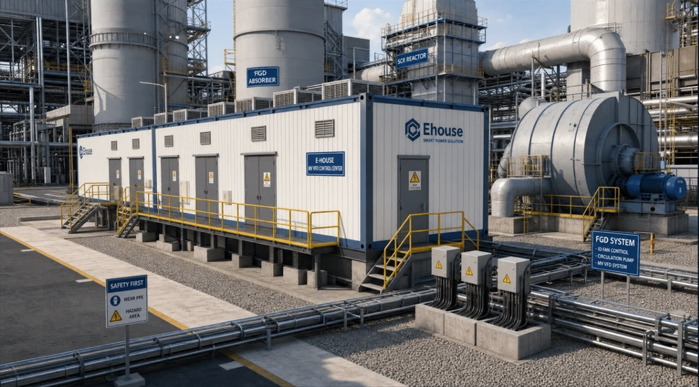
Prefabricated MV VFD E-House for power plant fan & pump drives — ID/FD/PA fan and circulation pump control for FGD/DeNOx projects.

ID/FD/PA Fan VFDCirculation PumpFGD/DeNOx4×1800kW

Auxiliary Power Used by Fans & Pumps
0 -70%
Auxiliary Power Reduction via VFD Retrofit
0 -25%
Faster Site Installation Time
0 -60%

MARKET CONTEXT · POWER PLANT AUXILIARY DRIVES

Growing Demand for MV VFD in Power Plant Applications

60–70% of power plant auxiliary electricity is consumed by fans and pumps — the primary targets for VFD energy savings
Energy Efficiency Mandates: National policies require power plants to reduce auxiliary power consumption by 15–25% through VFD retrofit
FGD/DeNOx Compliance: Environmental regulations drive new FGD and SCR installations, each requiring 2–6 large MV VFD motors
Aging Infrastructure: Existing power plants upgrading from DOL/soft-start to VFD for improved process control and reduced maintenance

8-12 Large MV Motors -Fans + Pumps-
4,000-15,000 kW Total Drive Capacity
E-House solution consolidates all VFD equipment into a prefabricated, factory-tested package — reducing site installation time and interface complexity

APPLICATION SCENARIOS · FAN & PUMP VFD CONTROL

E-House Drives Power Plant Fans & Pumps

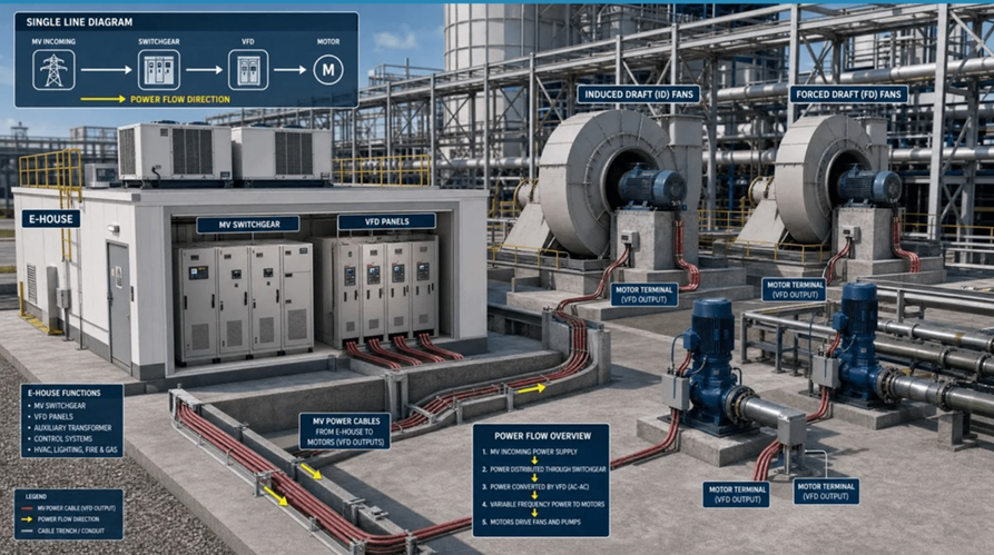
6 Target Motor Load Categories | 400-2,500 kW Motor Range per Unit | 6.6kV MV Voltage | 5-Step Power Flow: MV Incoming → MV Switchgear → MV VFD -AC-AC- → Output to Motor → Fan / Pump Load

ID Fan (Induced Draft)

1,000–2,500 kW · 6.6kV — Flue gas extraction, highest energy saving potential (30–45%)

FD Fan (Forced Draft)

800–1,800 kW · 6.6kV — Combustion air supply, energy saving 25–35%

PA Fan (Primary Air)

600–1,500 kW · 6.6kV — Coal pulverizer air supply, frequent load changes

Circulation Pump

1,200–2,000 kW · 6.6kV — FGD slurry circulation, high torque at low speed, 24/7 duty

Booster / Feedwater Pump

800–1,600 kW · 6.6kV — Feedwater booster, continuous duty with flow regulation

Condensate Pump

400–1,000 kW · 6.6kV — Condenser extraction, variable flow demand

PRODUCT OVERVIEW & TECHNICAL CONFIGURATION

Power Plant Automation House — Key Specifications

VFD Configuration: 4 × 1,800 kW MV VFD — 6.6kV Input, Medium Voltage Drive
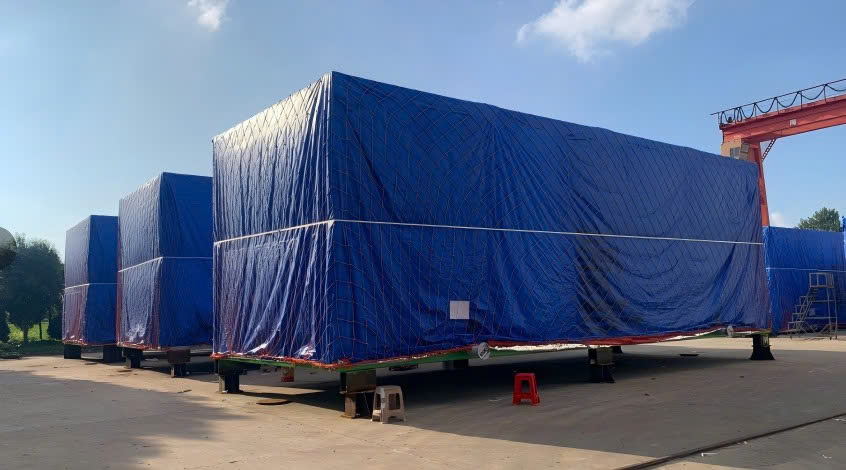
Dimensions -L×W×H-: 25,800 × 7,800 × 4,000 mm — Multi-Module Assembly
HVAC: 3 × 180 kW -N+1-, 28,600 m³/h Airflow per Module
Fire Protection: Novec 1230 / 2 Zones, VESDA + Smoke Detection

Protection: IP54 / IP55, IEC 61439 / IEC 62271
Control: PLC + SCADA/HMI, Remote Monitoring & Diagnostics
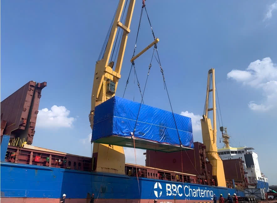
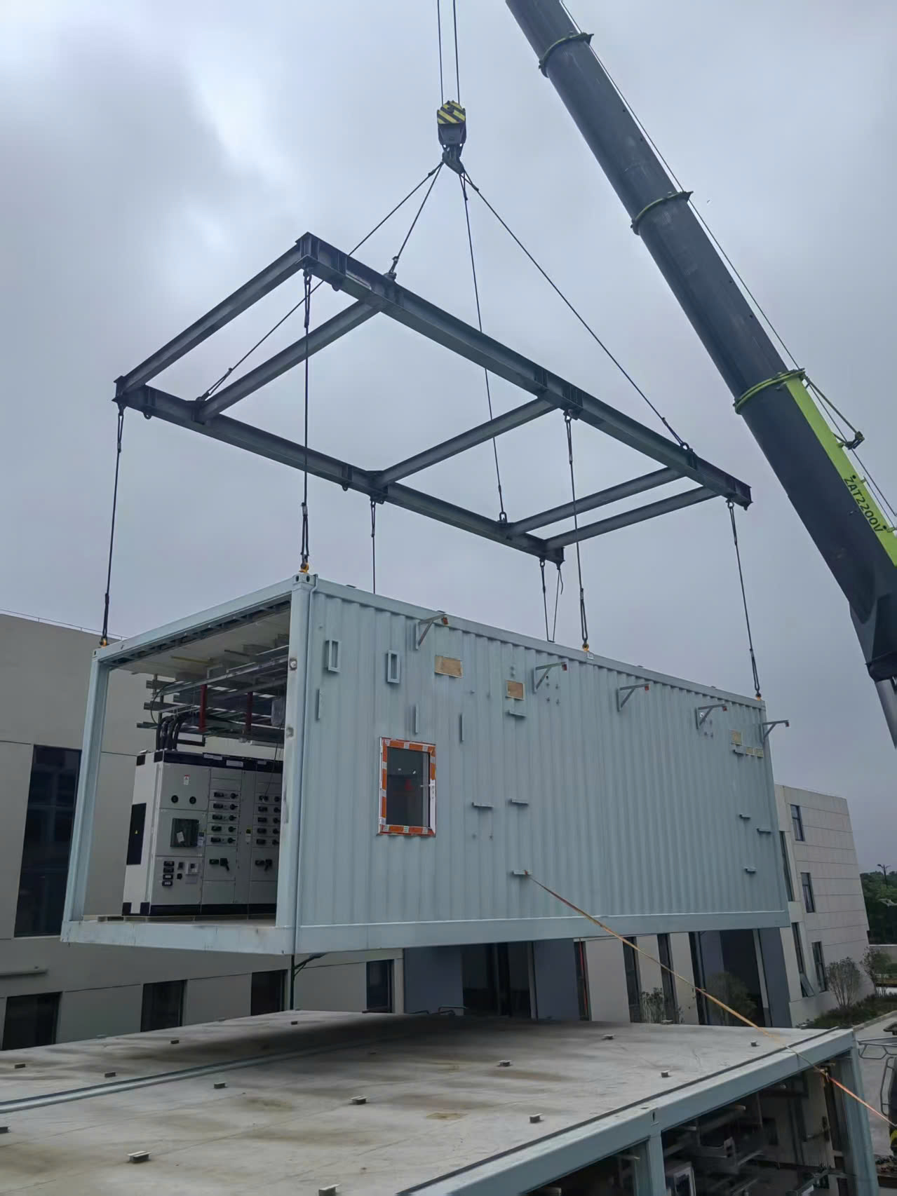
Delivery: Factory Prefabricated, FAT Completed, Plug & Play, 24/7 Operation, Remote O&M

FGD & DeNOx Project Application

Wet Limestone FGD System — Circulation Pump VFD Controls Slurry Flow Rate; ID Fan -Booster- VFD Maintains Flue Gas Pressure; Oxidation Blower VFD Adjusts Air for SO₂ Removal -20–35% Energy Saving vs. DOL-
Typical FGD/DeNOx Motor List: ID Fan -Booster- 1,800 kW ×2, Circulation Pump 1,600 kW ×3, Oxidation Blower 800 kW ×2, SCR Fan 1,200 kW ×2, Slurry Feed Pump 600 kW ×2

DeNOx / SCR System: SCR Fan Controls Flue Gas Flow Through Catalyst Layers
Ammonia Blower: Precise NH₃ Injection for NOx Reduction
Compliance Target: NOx < 50 mg/Nm³

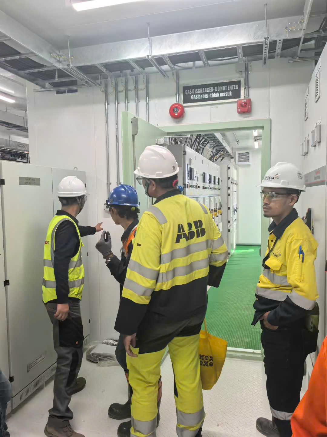
Medium Voltage VFD — 4 × 1,800 kW, 6.6kV Input / 0–6.6kV Output, DFE 36-Pulse Transformer -Integrated, Low Harmonic Design-.

Protection Class IP54/IP55 — Compliant with IEC 61439 -LV Switchgear/Controlgear- and IEC 62271 -HV Switchgear/Controlgear- assemblies.

PLC + SCADA/HMI — Remote Monitoring & Diagnostics; Siemens/ABB PLC Logic, Profinet/Modbus TCP, Cloud/OPC UA for Predictive Maintenance & Energy Analytics.

Precision Cooling — 3 × 180 kW -N+1-, 28,600 m³/h Airflow per Module, -5°C to +40°C Outdoor Design, Anti-Condensation Heating above 85% RH.

Novec 1230 Clean Agent Suppression — 2 Independent Zones -VFD Room + Control Room-, VESDA Early Smoke Detection, 120-Minute -R120- Fire Rating.

Steel + Sandwich Panel Structure — Rockwool 100mm -A1- Insulation, Bottom Cable Entry, -5°C to +40°C Ambient, 5–95% -Non-Cond.- Relative Humidity.

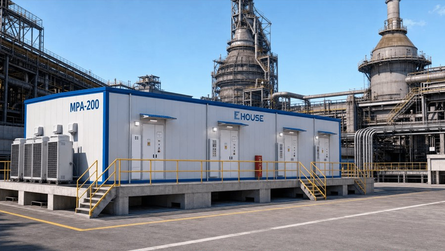
MPA-200B Power Plant Configuration

Overall Dimensions -L × W × H-: 25,800 × 7,800 × 4,000 mm | Configuration: 4×1800kW MV VFD per E-House Module | Design Standards: IEC 61439, IEC 62271, IEC 61800, NFPA 2001

SYSTEM ARCHITECTURE

Integrated Power & Control Architecture

Enterprise Level — Cloud Gateway, API, Remote Access
Supervision Level — OPC UA, SCADA Server, Historian
Control Level — Profinet / Modbus TCP, PLC Network
Field Level — Hardwired I/O, 4–20mA, Modbus RTU

Delivery Model & Engagement Process

5-Step Plug & Play Delivery: Engineering & Design -4–6 weeks- → Factory Prefabrication -12–16 weeks- → Factory Acceptance Test -1–2 weeks- → Transport & Install -2–4 weeks- → SAT & Remote O&M -1–2 weeks-. Total Project Duration: 5–7 Months -vs. 12–18 Months Traditional-, 40–60% Site Time Reduction, Single-Vendor Responsibility.

More infomation

Detailed Specifications

Other Projects